The CCE-4 is an adjustable step controller that can control 2 to 4 fixed steps and a modulating one.
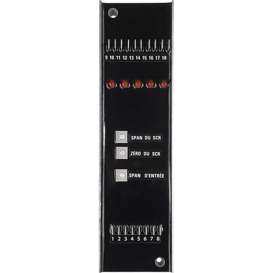
Description
- Adjusting SPAN for the number of steps.
- Adjusted the input SPAN for the signal type.
- Zero adjustment
Features
| Modele | CCE-4 |
| Voltage | 19 to 27VAC |
| Operating temperature: | +10C to +45C (+50F to +113F) |
| Storage temperature | -30C to +80C (-22F to +176F) |
| Control signal | -Analog 0-10 VDC -Analog 4-20 mA |
| Dimensions | 2″3/16 x 8″1/4 |
| Connection | Tab 0.250 |
| Mounting | 2 holes mounting |
| Fix output | Triac 0.5A @ 120VAC |
| Moduladed output | 24VAC |
| Warranty | Standard two years limited warranty |
Applications
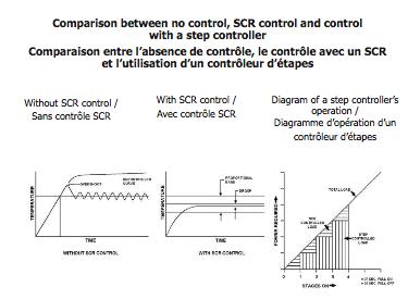
The CCE-4 stage controller from Cristal Controls is designed to activate several heating elements as linearly as possible according to its signal
For example, the CCE-4 controller with 4 fixed steps and 1 modulating output and each controls 20% of the total load.
The first output is the modulating step, modulated proportionally to the input signal. The modulation is of variable time width (pulsed) or analog (0-10Vdc). This output smooths the transitions between the other fixed stages and requires a semiconductor power control which can allow thousands of state changes per day and fast.
When the modulated output reaches its maximum level, the stage controller activates a fixed output and lowers the modulated output to its minimum level. The process is repeated until all fixed stages are activated and the modulating output reaches its maximum level. The modulated output repeats its modulation on 20% of the input signal according to the number of fixed stages used.
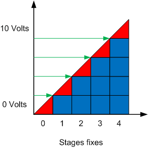
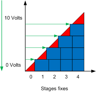
The image above shows an ideal step controller. The red triangles represent the contribution of the modulating stage and the blue squares represent the contribution of the fixed stages. We can therefore see that close to 0V, only the modulating stage controls the heating while near 10V, the 4 fixed stages add to the contribution of the modulating stage to reach 100% of the heating capacity.
The green arrows indicate the places where the control signal makes the transition between the modulating stage and the fixed stages. A problem arises with this representation, if the control signal oscillates slightly on each side of the green arrow.
For example :
Signal = 1.99V > Étape modulante = 99% > Étape fixe = OFF
Signal = 2.01V > Étape modulante = 1% > Étape fixe = ON
We can see that a slight change of signal, in one direction or the other changes the state of the modulating stage in a significant way to compensate for the use of the fixed stage. The fixed step is therefore found to be modulated if the signal flickers around the transition point which gives inappropriate behavior for a power control of the contactor type.
The solution to this type of problem is to "delay" the transitions with a hysteresis algorithm. We therefore ensure that the input signal continues to rise before initiating an additional fixed stage. In the same way, we also make sure that the input signal continues to go down before deactivating a fixed stage.
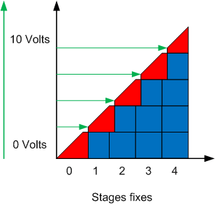
The example on the left shows the step controller as the signal increases. Note that the modulating stage is slightly capped at 100% before activating a fixed stage. Once the fixed step is activated, the modulating step starts at a modulation rate greater than 0% to keep all of the outputs as linear as possible with respect to the input signal.
The example on the right shows the step controller when the signal decreases. Note that the fixed step is kept ON for a certain variation of the input signal even if the modulating step has reached 0%. Once the fixed step is disabled, the modulating step starts at a modulation rate close to 100% to also keep all of the outputs as linear as possible with respect to the input signal.
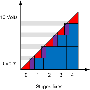
If finally, we superimpose the graphs for the signal which increases and that of the signal which decreases, we see that the number of steps at the output is on average similar to the graph of the ideal step controller. On the other hand, there are certain portions of the signal for which it is not possible to predict the state of the output without knowing the state of the signal slightly before. This memory effect prevents having a number of charges at the output perfectly equal to the input signal at all times, even if this is the case on average.


